
Substance Painter Tutorial
Courtesy of Zach
Primer and Tips
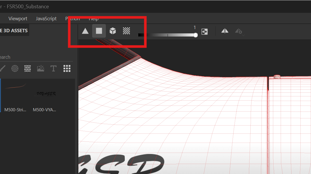
Substance Painter allows you to use Perspective View or Orthographic View, F5 and F6 respectively. I almost always use orthographic view.
Substance Painter has quite a few default keybinds. The ones I use the most are;
Alt + LMBRotation. This allows you to rotate the viewport around the axis of wherever the mouse isAlt + MMBPanning. This alows you to pan the viewport up/down/left/right relative to wherever the mouseAlt + RMBZoom. This allows you to zoom the viewport in/out relative to wherever the mouse is at that time. Can also simply be done with the scroll wheel on it's ownControl + Alt + RMBMaterial viewer. This selects whatever material is located under your mouse pointer at that time. Helpful for knowing which material is where on the modelShift + Alt + LMB. View snapping. This will snap your view in 90 degree increments as you drag your mouse. Works in all axes
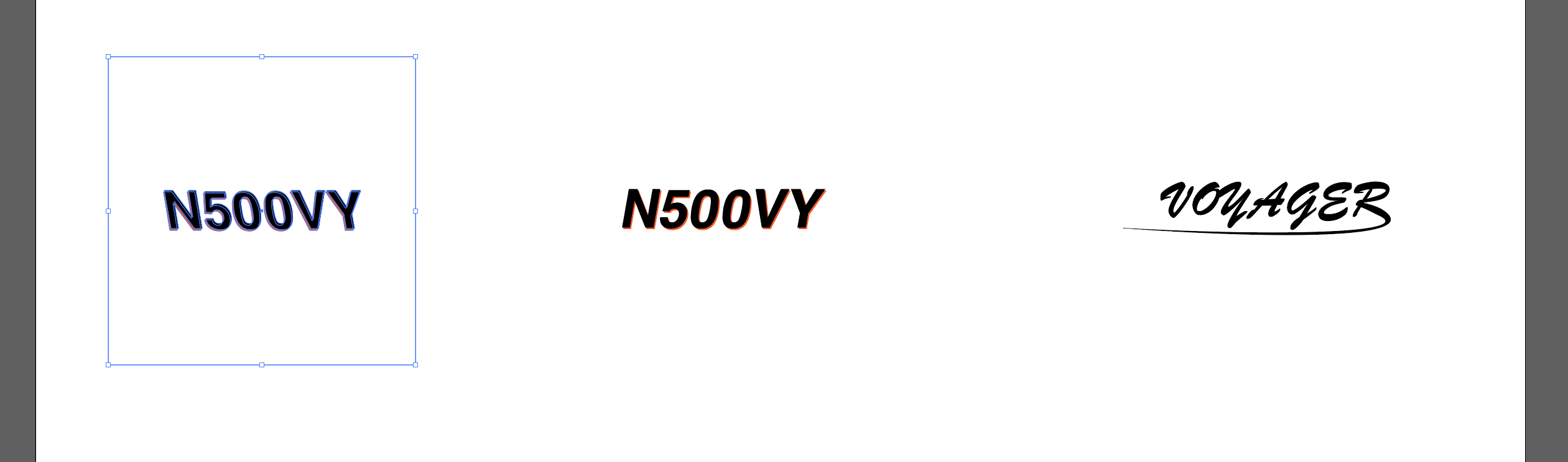
Substance Painter likes perfectly square images. When creating a PNG decal for stripes, logos, or anything else, make sure it is perfectly square. My preferred way of doing this is to add an invisible square around each asset that I make. For example, an N-Number, I'll place it inside an invisible square and export it together as one. Otherwise, the scale on the XYZ directions gets skewed and messy.
Substance Painter is pretty resource hungry. The resolution you set at the time of project creation is not what you are limited to on export. So, if 4096x4096 is bogging down the program, you can set it as low as you want — It will look blurrier in the viewport, but you can export it at any resolution that you want, all the way up to 8K.
Black Masks and White Masks are your friend, as is Polygon Fill
I don't recommend painting via "Paintbrush" or similar. Creating "Decals" or "Stencils" in another program such as Illustrator will make your life 10X easier, and yield a much better looking end result
Setting Up the Project
When you open up Substance Painter, you can either open a preexisting project, or create a new one.
For the purpose of the M500, you'll want to open the preexisting project .spp since FSReborn has provided all of the necessary overlays already for things like the boots, screws, etc that you'll want on top of your paint. It's not set up wholly for UDIM though it seems, which is a bit of a bummer — but not the end of the world with Substance Painter in comparison to Blender.
For the purposes of the tutorial and for future reference though, I'll explain how to set up a new project as you'll need that for other aircraft without a paintkit.
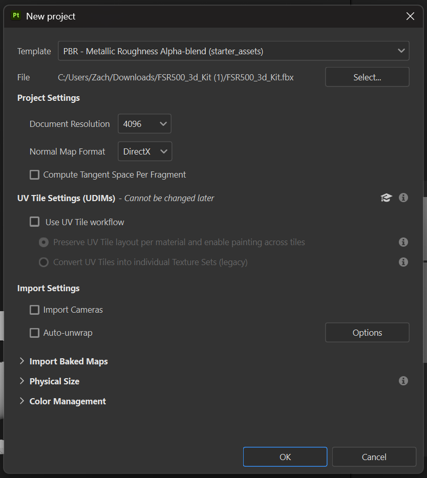
At the top left, go to File>New, which opens the New Project dialog window.
-
Template. You'll want to use thePBR - Metallic Roughness Alpha-blend (starter_assets)template. -
File. You can choose the model by pressing theselectbutton. You will almost always want an.FBXmodel -
Project SettingsDocument Resolution. Here you can choose the default resolution of the textures that you see within the viewport (as explained above in the primer + tips)Normal Map Format. Always keep this set toDirectXCompute Tangent Space Per Fragment. No need to have this checked
-
UV Tile Settings (UDIMs)Use UV Tile Workflow. Check this if you want to use UDIMs for materials. If checked, also select thePreserve UV Tile....option
-
Import SettingsImport Cameras. Keep this uncheckedAuto-unwrap. Keep this unchecked
-
Import Baked Maps,Physical Size, andColor Management. These dropdown menus can be left untouched unless you have a specific reason to change anything in there
Once all of that is set up, you're good to go by pressing the OK button which will launch your new project into the program
Interface Familiarization
At first glance, Substance Painter will look extremely overwhelming — and frankly, it is. The majority of Substance Painter (and the entire Substance family of programs) is geared mainly towards the creation of game assets, renderings, and full start to finish asset creation... hence, 75% of the features we won't even need to know exist. The good part here is, it is so powerful, that it makes our job when creating liveries very easy.
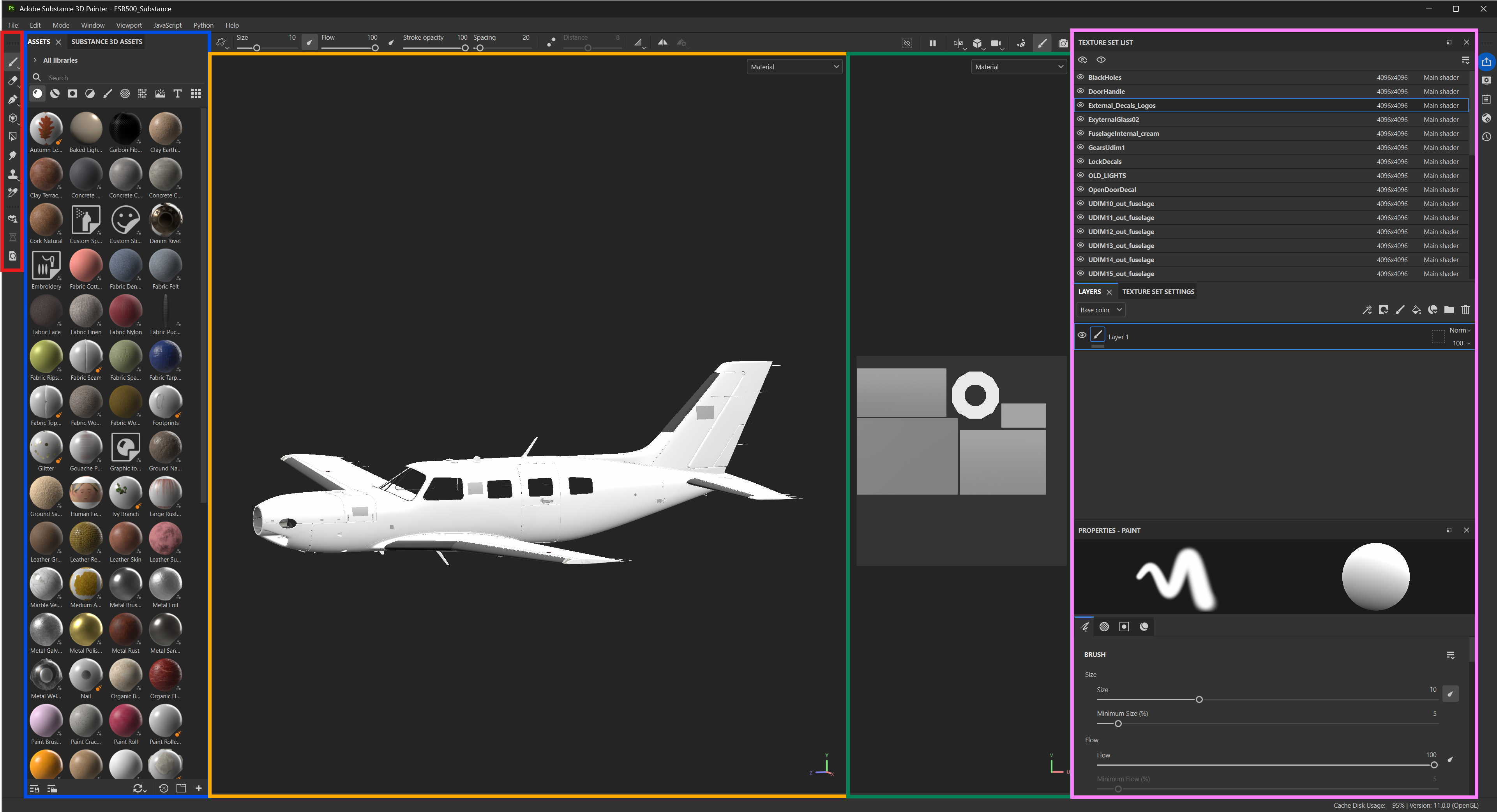
Now that you have loaded in your project (or created a new one), you'll see the default SP layout. From left to right we have:
-
🔴
Left side toolbar. This houses a variety of tools such as the brush tool, eraser, polygon fill, etc -
🔵
Assets Library. This houses all of Substance's built-in assets, user-imported assets, and Substance's online asset viewer + community asset viewer -
🟡
3D Viewport. This is where you see your 3D model, and any textures applied to it -
🟢
2D UV Viewport. This is where you see the square with shapes in it. This is your UV map for the selected material slot -
🟣
Right Side Toolbar. This is where most of the magic happens. You have yourTexture Set List, which lists all of the material slots on the imported model. Below that, you have a variety of tabs forLayers,Texture Set Settings,Properties, etc.
Decal/Stencil Creation
Now that we have our project loaded in, the first step is to create our decals/stencils. These are the art that we project onto the model — reg numbers, stripes, logos, all that fun stuff.
You can use just about whatever program you want, free or paid, as long as it is capable of exporting your art into a high-resolution .PNG with transparency. Personally, I use Adobe Illustrator since it is a vector program, but other bitmap programs such as Photoshop, Paint.net, etc will work just fine.
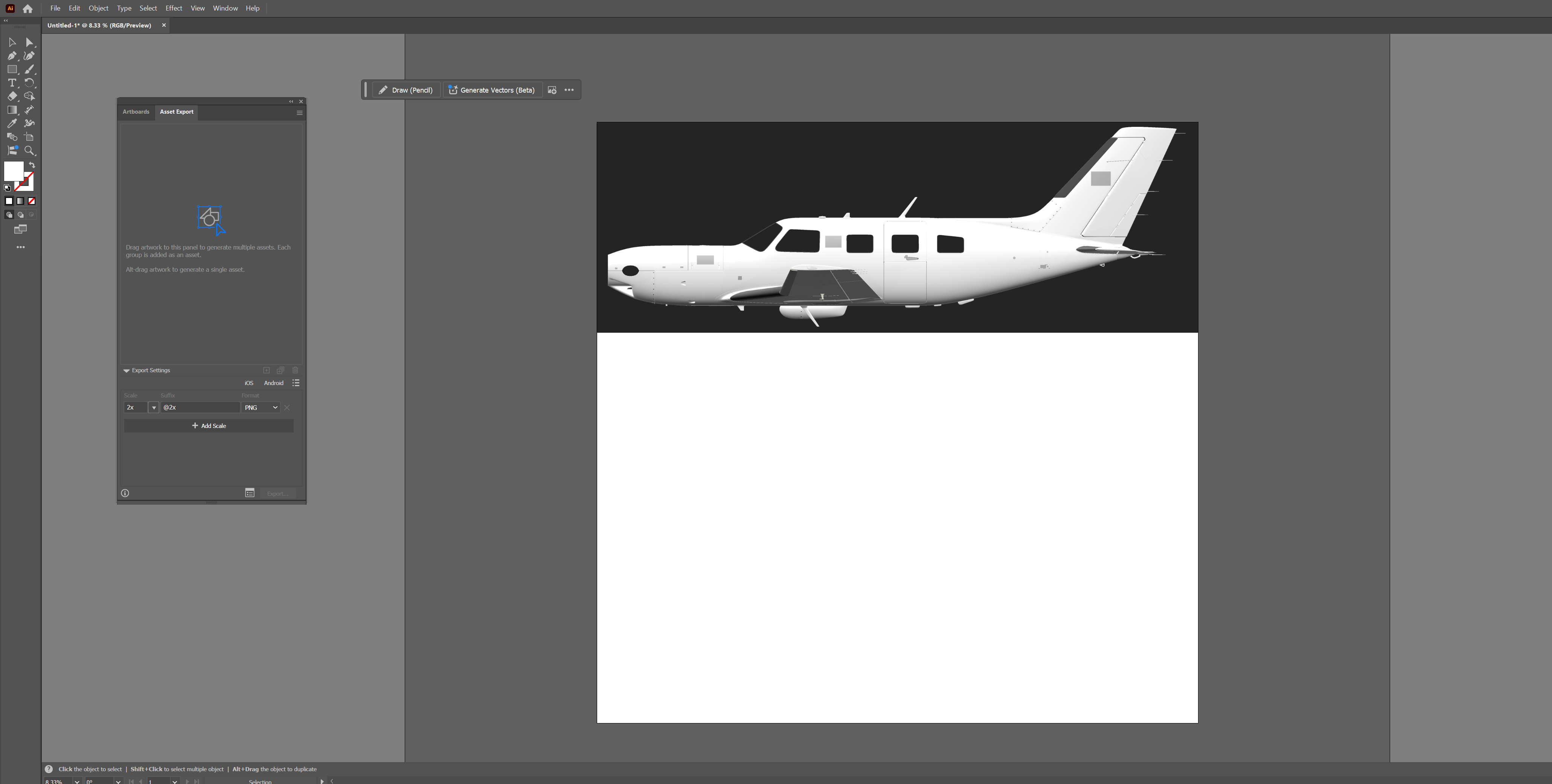
To begin, I like to take a side shot of the aircraft in orthographic mode. Then I place that into Illustrator, so I can use that as a base for creating the art that is project onto the model
From there, there are a few different directions you can go.
If you're just freehanding a design, there isn't much else to do besides starting on that.
If you are trying to replicate a real world livery, you'll want to find a photo that is as perfectly side-positioned as possible. Then you can import that, position it over your fuselage screenshot, and lower the opacity to see the underlying screenshot. Note, it is impossible to get a perfectly orthographic photo from a camera or picture online, so some inferencing or adjust will be necessary.
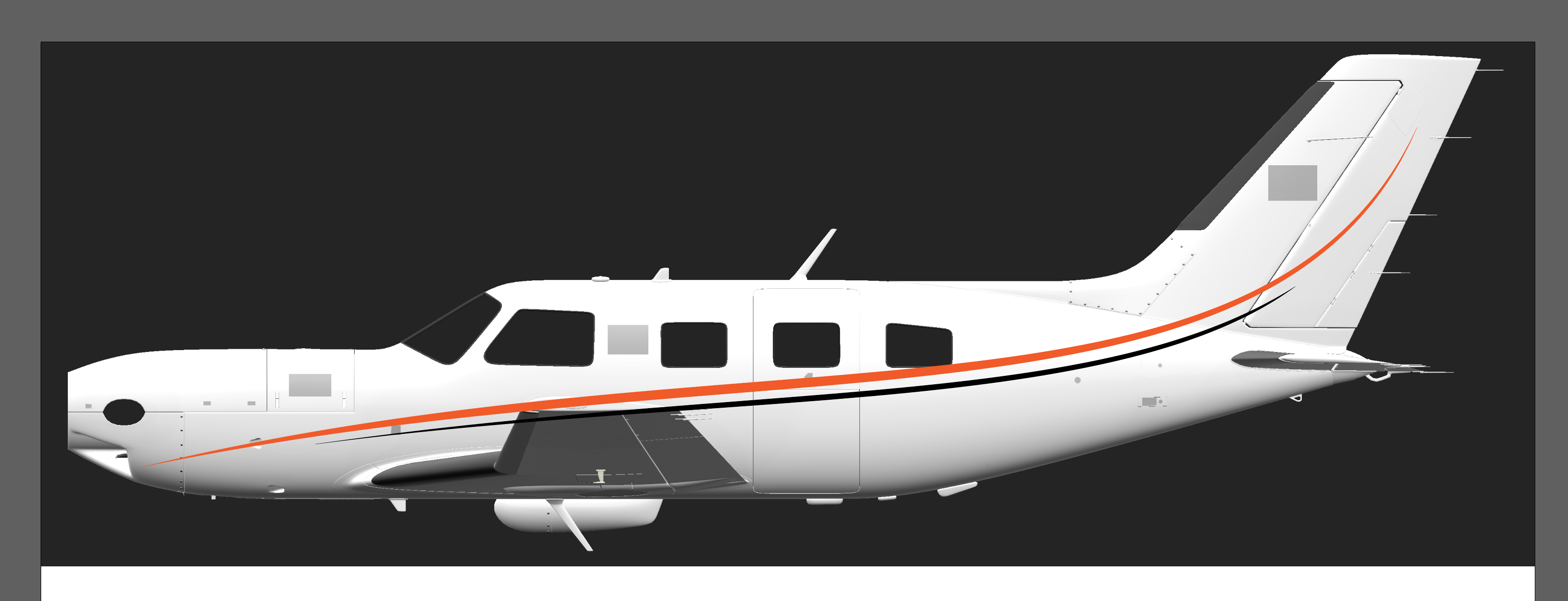
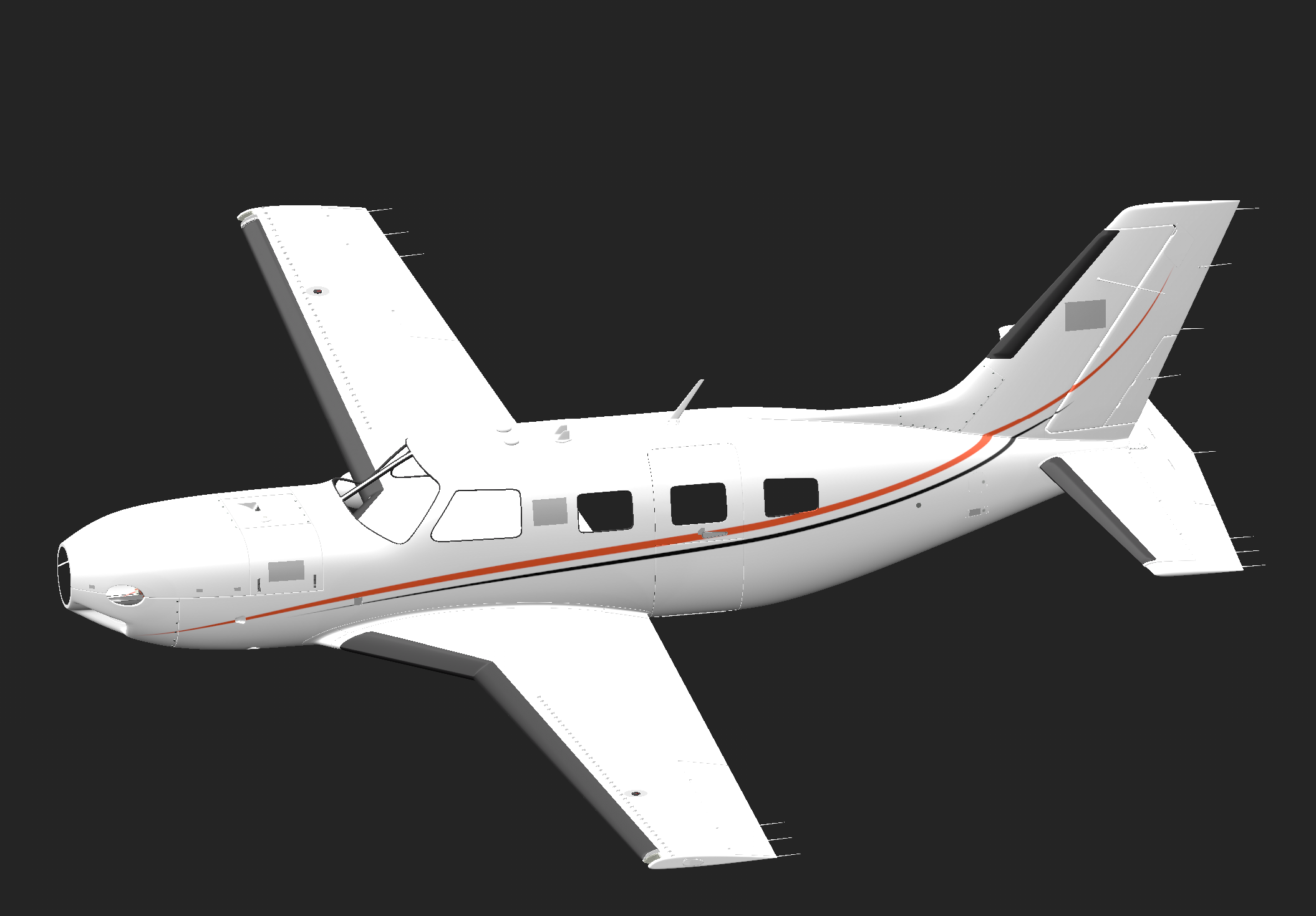
For the sake of this tutorial, I will just create some basic stripes that we can project onto the fuselage. I'll also add in a logo and an N-Number for the sake of the tutorial as well
You'll see below how I have a perfect square (invisible) around the right side N number stencil, so that SP handles it without skewing
If you want to follow along with what I'm doing exactly, here are the assets from above that you can use in the below steps as I go through the tutorial
Asset Importing
Once you have your assets created + exported (or if using mine above), you can now import those into Substance Painter.
To do so, ensure that you have a project open — then, click File>Import Resources. The Import Resources dialog window will pop up. Click the Add Resources button, and select all of your PNGs. When done, it should look something like this;
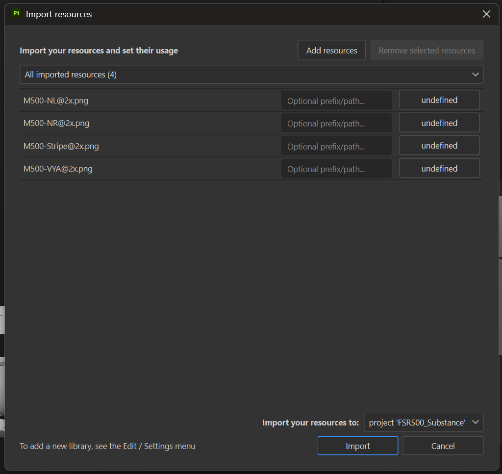
You'll notice that next to each resource/image/PNG is a box that says Undefined. You can click on each one and change that to Texture prior to importing. Once all of those are set as textures, click the Import button.
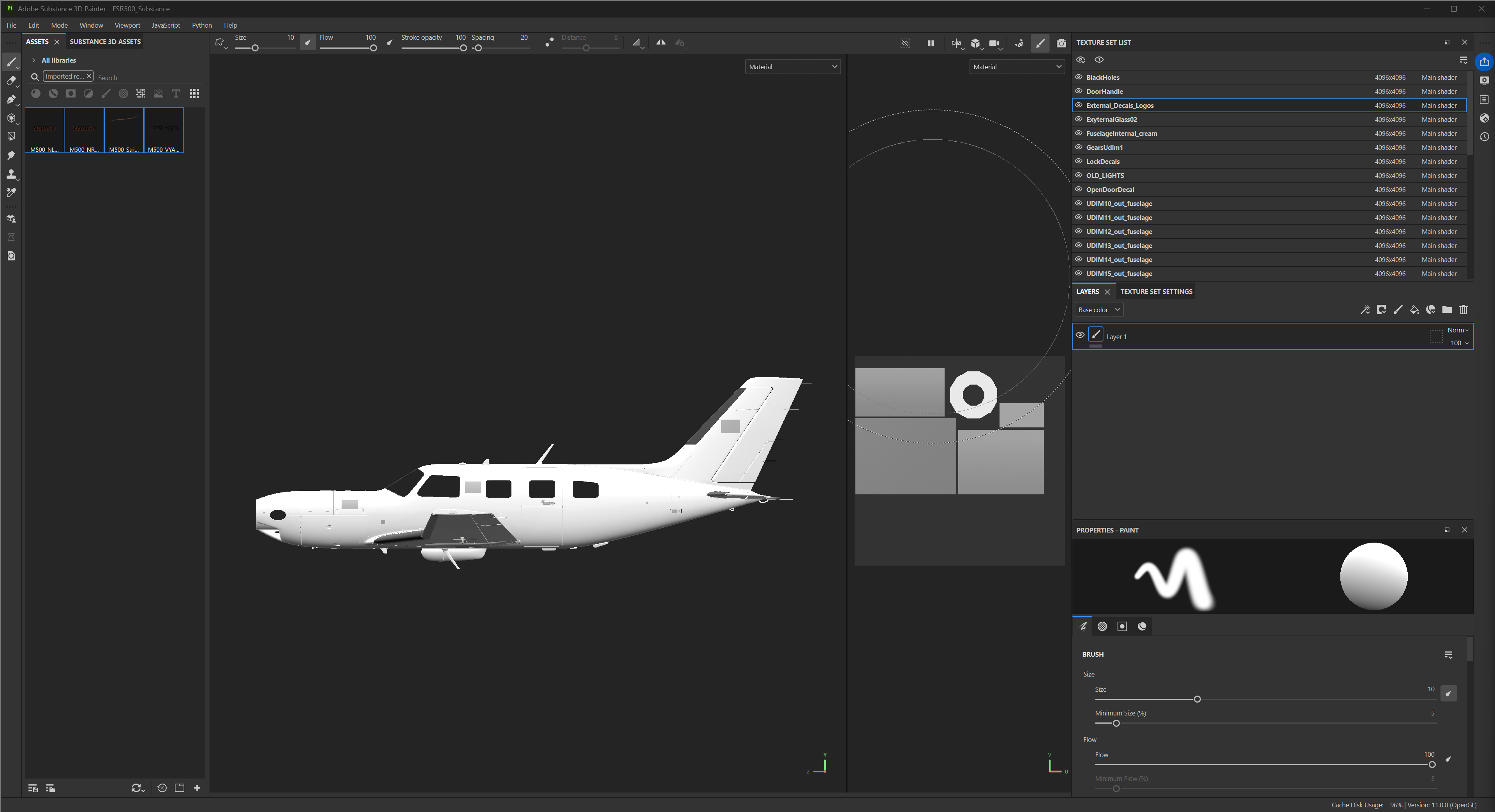
You'll now see that your Asset Explorer on the left side has only your 4 new assets that we just imported. Since you won't need any other assets at this point, that is fine. Everything that you import will always be housed in this Asset Explorer.
Putting Imported Stencils on the Model
Now that we have our stencils imported, we can apply them to the model.
Let's start with the stripes. Using the Shift + Alt + LMB keys, we'll snap our viewport to be looking at the left side of the fuselage in orthographic mode. It'll look like this;
Now, we can go over to the Asset Explorer on the left, and click + drag our stripes stencil image onto the fuselage of the M500
As you let go of the mouse, a little window will pop up. Click Base Color
Note, wherever you place the image will be the material that it is located on at first. You can see these materials as you drag it around before releasing the mouse — by default, they show up as a red wireframe
With the stencil now roughly on the fuselage, there are a few things we need to take care of. These are very important, and are done every time we add a new stencil onto a model.
On the right side, you'll see that your stencil is now at the very top of your Layers. As can be inferred, these layers act exactly how you'd expect — what's on top is on top, anything below that is covered by anything above it.
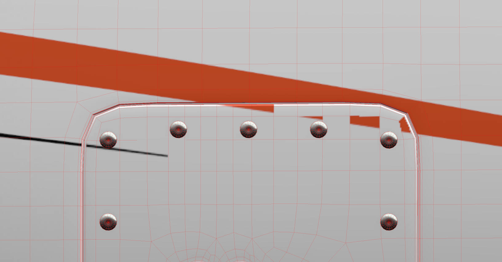
In cases like UDIM27_out_fuselage, you'll see that FSReborn included some overlays for base parts that we want on top of our paint/livery, such as the deice boots, screws, rivets, etc. In cases such as that, we'll drag our painting layers underneath the overlay layers.
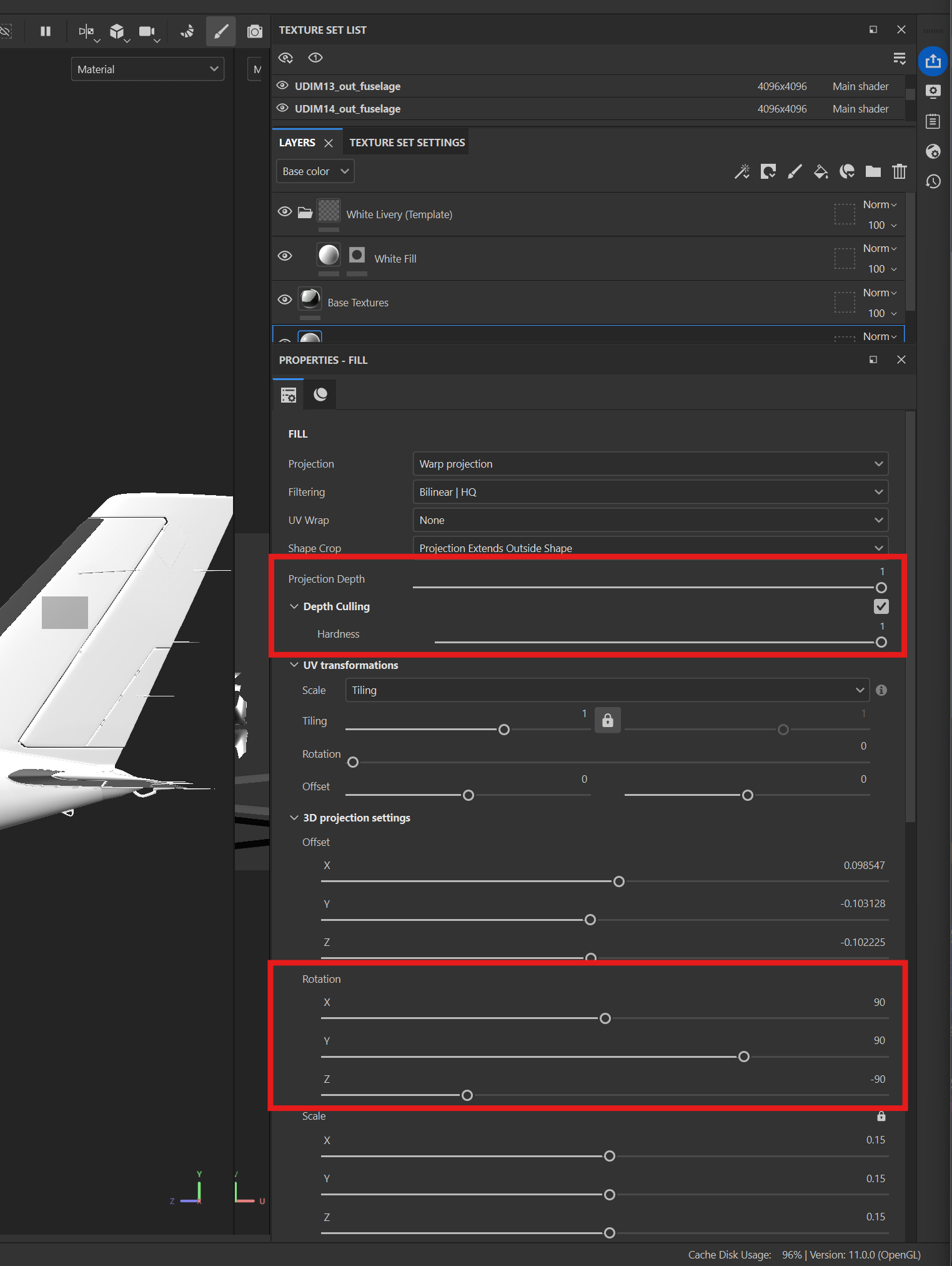
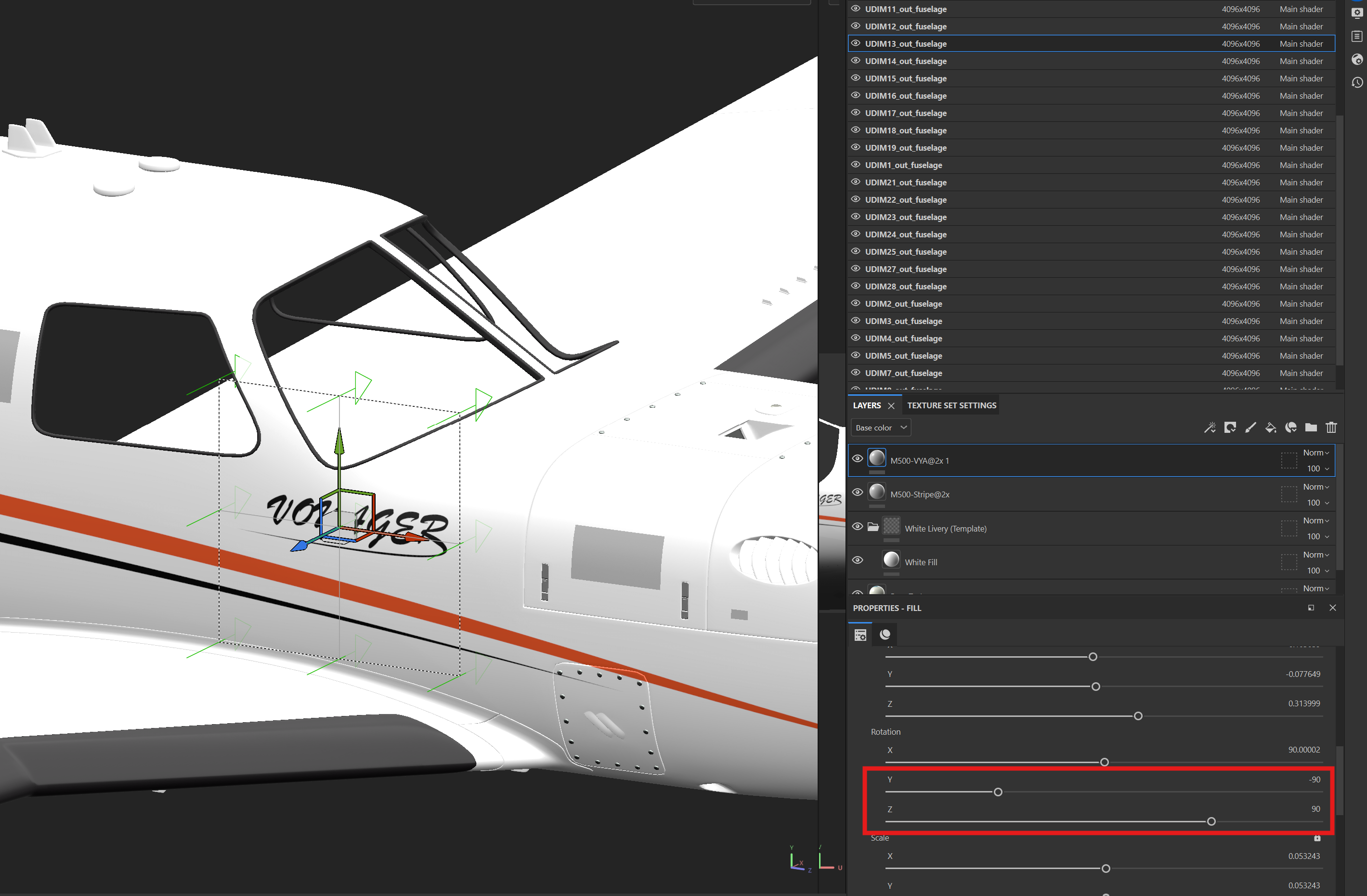
With our paint layer selected, we'll go down to the bottom right in the PROPERTIES - FILL tab. Set the Projection Depth and Hardness sliders all the way to the right, at a value of 1.0.
Under the 3D Projection Settings dropdown, we'll set the Rotation X value to 90, Rotation Y value to 90, and the Rotation Z value to -90. This creates a perfectly flat projection. Note, these values change depending on how you are wanting to project onto the model — for example, if you want to project something from the right side, Rotation X remains the same, Rotation Y changes to -90, and Rotation Z changes to 90.
When done, your PROPERTIES - FILL tab should look something like this;
From here, we can go ahead and resize the stencil now to fit the fuselage as intended. In the case of the M500, since there are so many materials, it is a little difficult as non-UDIM setups paint only on one material at a time. I'll have to check with Raul as to why the paintkit isn't set up on UDIM, and why the FBX won't import under UDIM either...
Anywho, we will use the resize tool and move tool to adjust sizing and positioning
Once you've clicked the resize tool from the upper toolbar, you can click and drag the top right corner of the grey square (pointed to by the arrow in the photo below) to resize up or down
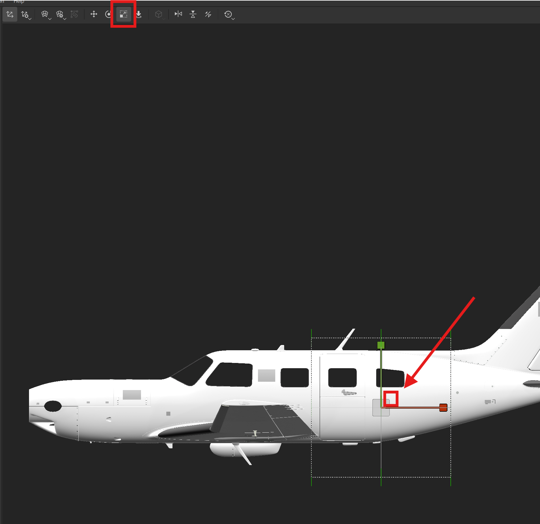
The move tool is in the same upper toolbar. When that is in use, you can click and drag the green arrow to move up and down, red arrow for left and right, and the blue dot in the center for both axes.
Tip... in cases like the M500, for positioning, sometimes it is helpful to copy and paste your paint layer onto other materials, like the tail and/or nose, to help with positioning rather than constraining yourself to positioning with only one material. Just make sure that once it's moved to where you want it, that all of the materials have the same positioning
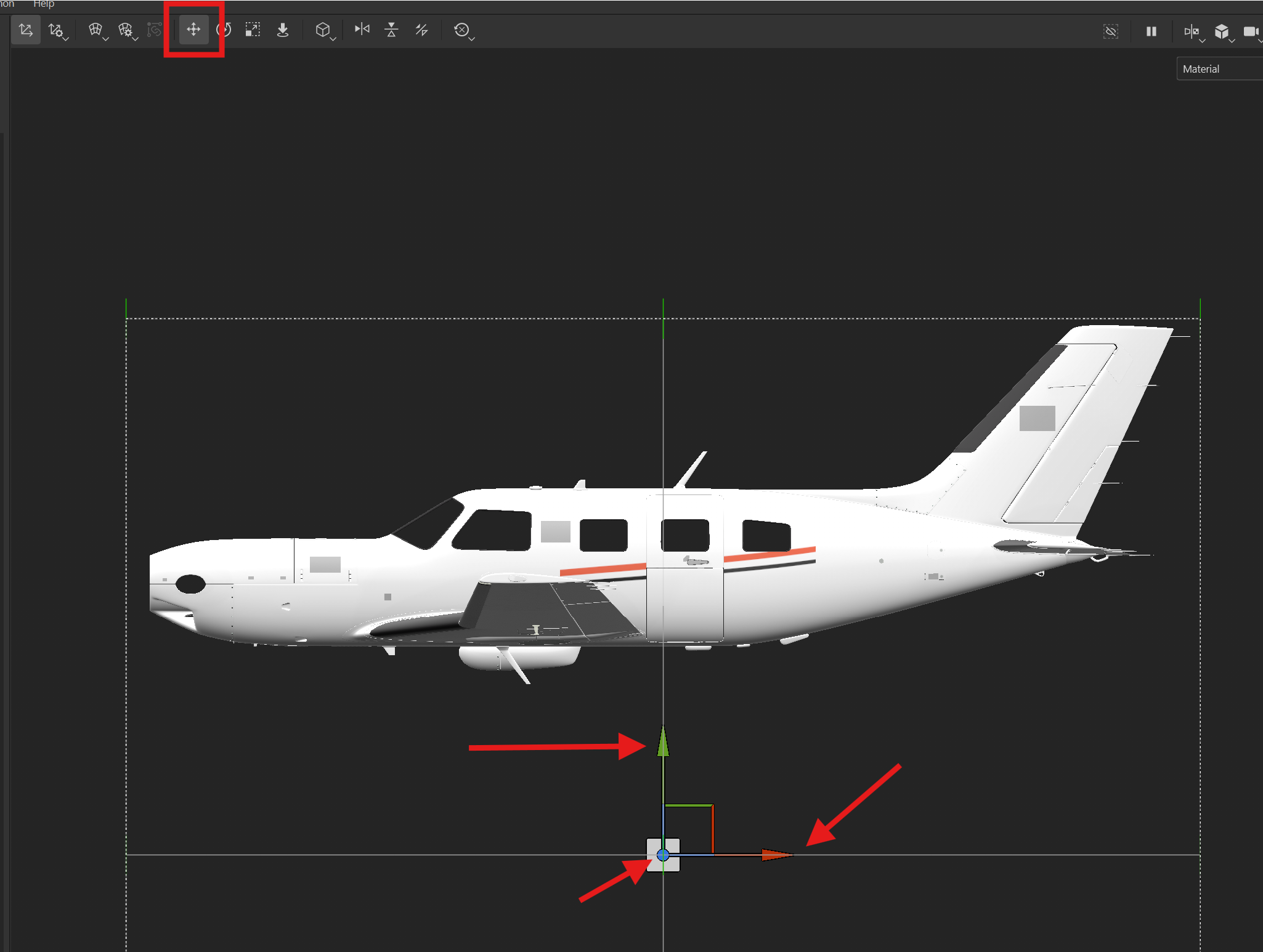
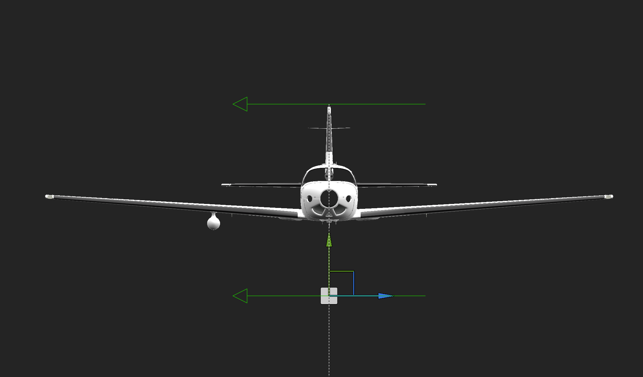
Now that it's positioned where you want it, use the Shift + Alt + LMB again to look at the model head-on. With the move tool, we'll then click and drag the blue arrow so that it is roughly centered down the middle of the fuselage. This ensures that the texture is applied to both sides. The green hollow arrows that you see are a generalized idea of how far the texture will extend in the viewport in terms of mirroring and coverage
From here, we can start copying our stencil and pasting it onto other material slots so that we are covering all of the necessary material slots
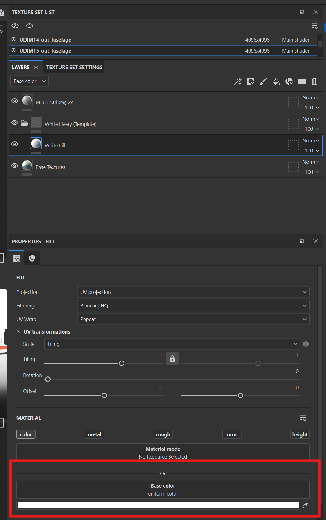
At this point, it'd also be wise to decide on what ou want your base color to be. Off the bat, the M500 paintkit comes with a plain white base color. If you want to change that, you can add a new fill layer (paintbucket icon) and place it under your stripes layer, or, just edit the color of the White Fill layer that FSReborn has provided
Now we have our stripes on all of the necessary materials
With the M500, you will probably have to futz around a bit with the layering in order to make sure that the provided overlays don't get covered up by the paint. You can also do this in post processing once our textures are exported, in a program like Photoshop or Paint.net You can also use things like a Black Mask or White Mask with Polygon Fill to mask out areas as desired, which I'll talk about later on below Now that our stripes are all good to go, we can add a logo under the cockpit window.
Just like the stripes, we'll drag it onto the model, set the Projection Depth, Hardness, and Rotation X, Y, X. Then we will scale it and move it to it's desired spot
However, you'll maybe realize at this point that we don't want it mirrored, since it is text — it would look reversed on the other side. So for that, we can skip moving it down the center of the fuselage.... in fact, depending on the size, we might even have to move it away from the fuselage so that it is only painting it on the desired side.
![]()
With our logo now on the right side, we can copy and paste that layer.
This duplicate layer can now be moved to the right side of the fuselage via the move tool and it's blue arrow to ensure that we are only translating it from left to right
If nothing is showing up on the right side, that is because the right side is on a different material. So, we can Control + Alt + RMB in that area to select that material, and then paste the logo layer into there and move it over.
To fix it from looking backwards, change Rotation Y to -90 and change Rotation Z to 90.
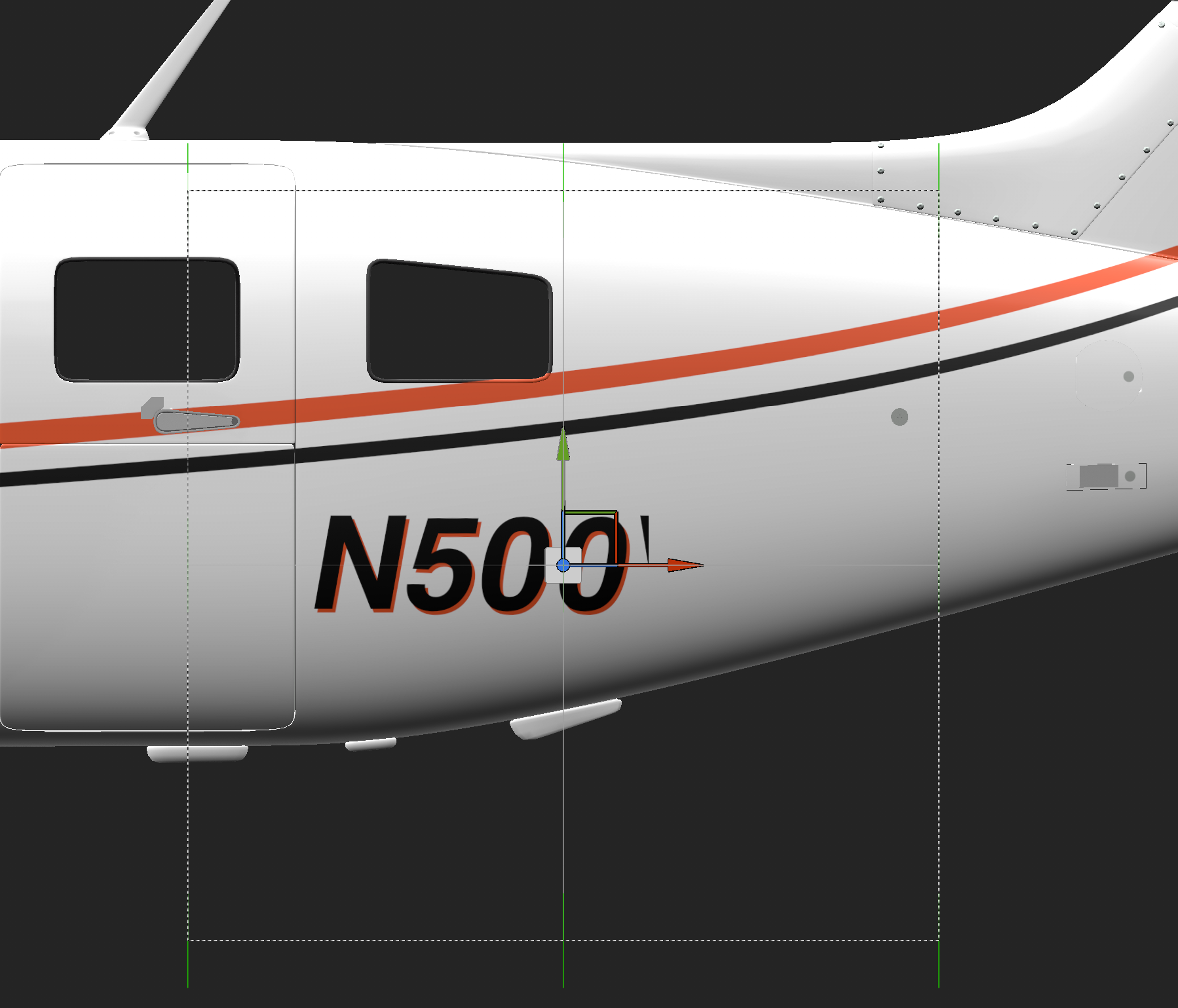
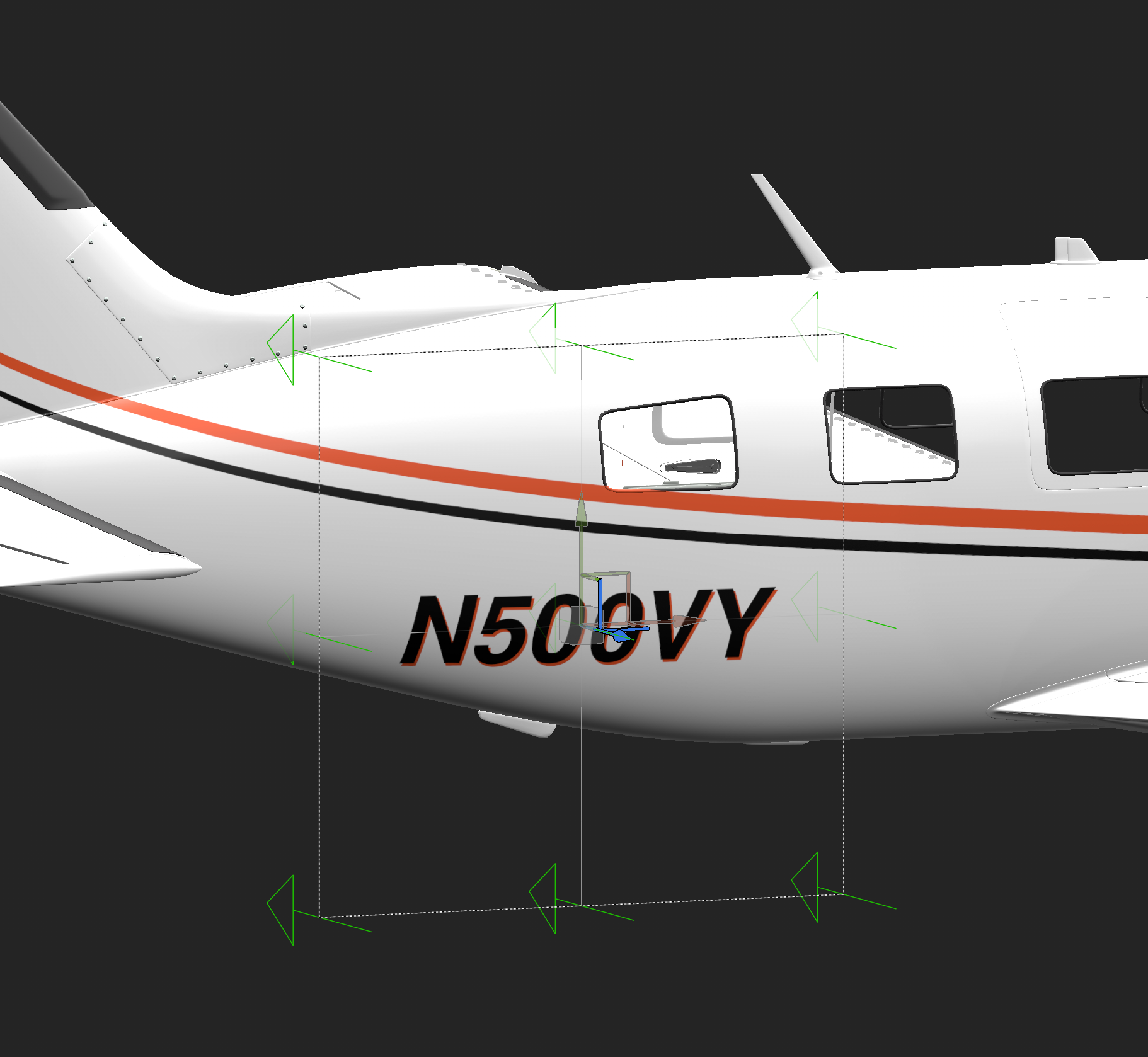
Finally, all we have left is the N-Number. We'll start with the left side. Since the N-Numbers I made for this tutorial are slanted, we have a stencil for the left side, and a stencil for the right side, to ensure that they are always slanted towards the aft of the airplane.
After using the above methods to place the N-Number, it'll look like the below photo. By now, you should be getting a good idea for how to place and adjust stencils onto the model
You may also be noticing that, similar to the stripes, depending on the size of your N-Number you will need to copy and paste it to the neighboring material if it is cut off
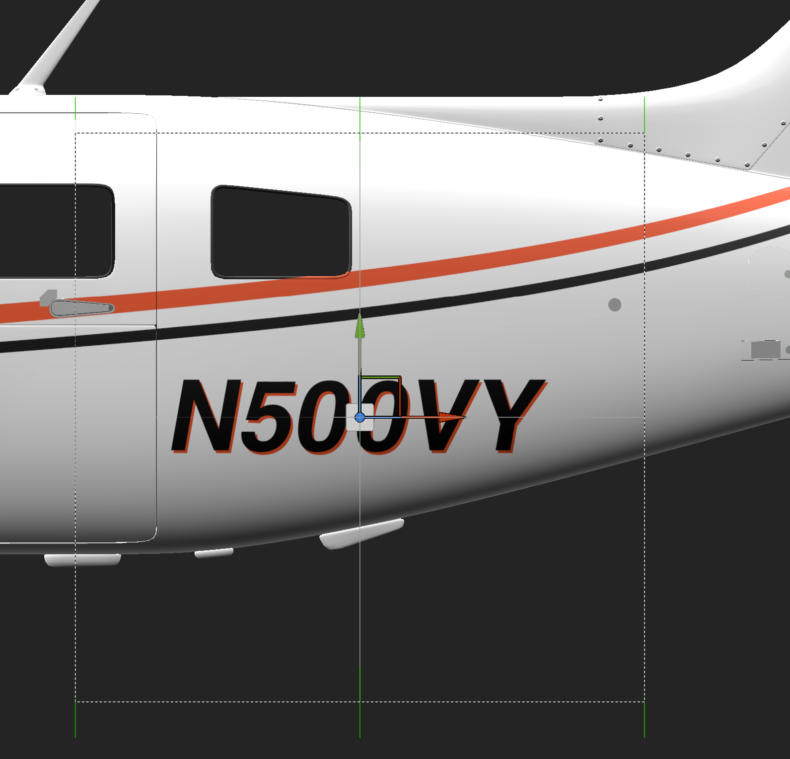
For the right side, we'll paste this layer again onto whatever materials cover that right side. Likely it will be 2 materials.
Similar to the logo on the nose, we have to translate the stencil to the right side with the move tool, and also flip the Y and Z rotations for each layer on each material on the right side.
Now that the stencils are placed, we can replace them with the right side stencils to have the correct slant and orange shadow orientation.
To do so, click on the layer for the right side N-Number, and scroll down in the PROPERTIES-FILL tab. Drag and drop your right side stencil from the Asset Explorer onto the Base Color box to replace it.
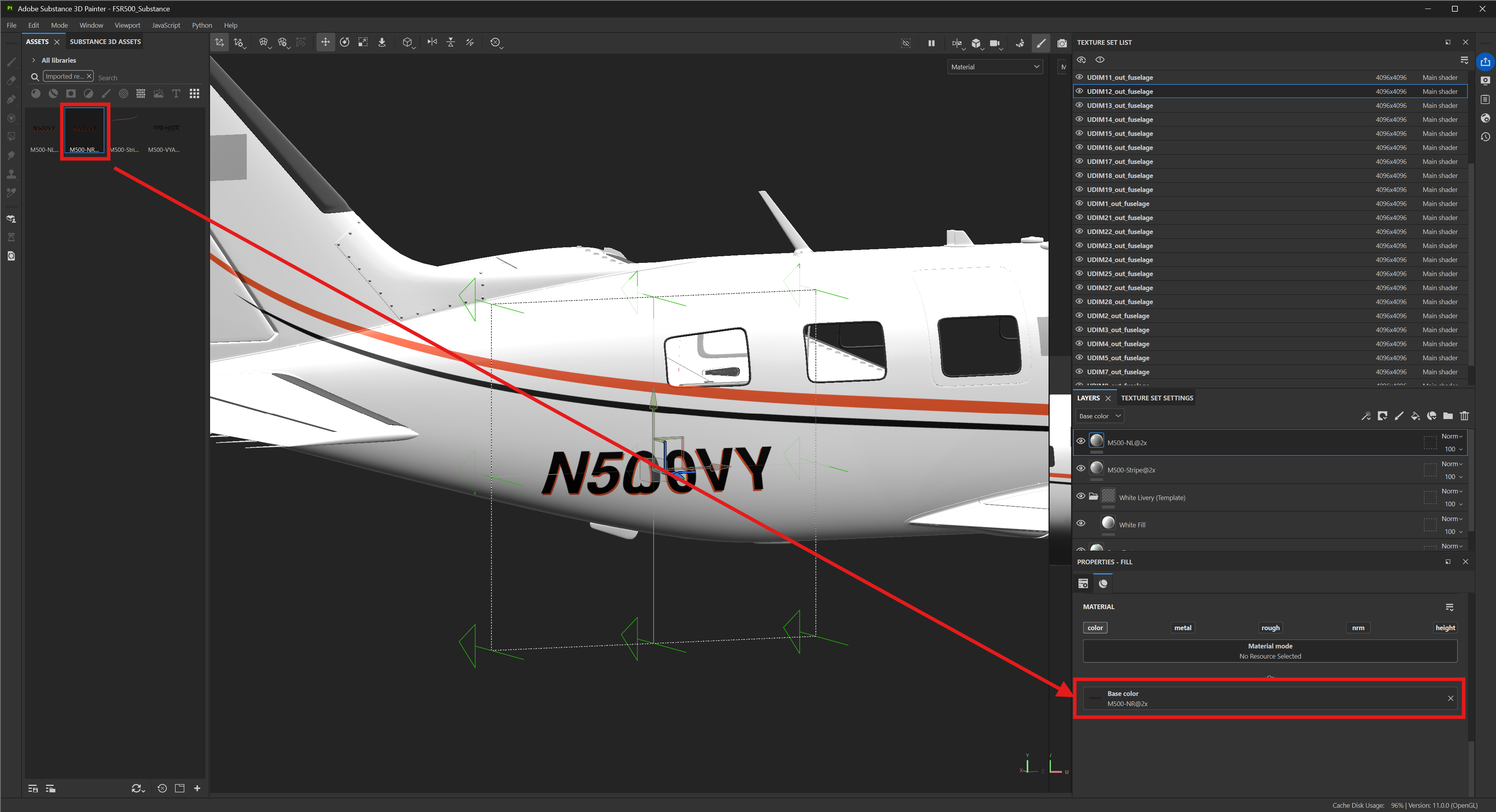
Rinse and repeat for the other material slot on the right side, if your N-Number is covering two materials
And that's it! You now have a neat white livery with custom stripes, logos, and N-Numbers. Now it is time to export
Exporting Textures
Go to File>Export Textures or press Control + Shift + E to bring open the Export Textures dialog window.
You will be presented with the initial window, the Global Settings tab.
You'll want to select your output directory, and then your output template. For now, you can use Document Channels + Normal + AO (With Alpha.
File type will automatically export as PNG, so no need to touch that.
Size is up to you, for UDIM-type applications like this, 2048x2048 is fine, or 4096x4096 is too albeit at a higher VRAM cost in the sim. 8192x8192 is not really necessary unless you want something super duper ultra crisp. For other non-UDIM aircraft like the Vision Jet, you'll want 4096x4096 at a minimum IMO. Any less than that and it's pretty blurry in most cases.
Padding is also up to you, and a very "variable" variable. It depends on how you want to put your textures together in the end.
-
Dilation Infinite. This option creates an infinite dilation between UV islands, giving you one solid texture with no transparent areas. This is used most often, especially if you have a paintkit in Photoshop that provides overlays on top during post processing -
Dilation + Transparent. This option is for when you want transparency between UV islands, but also a little dilation off of the UV island edges to prevent any visible seams at low zoom levels in the sim. I would recommend no less than a value of3for this. -
Dilation + Default Background Color. Similar to Dilation + Transparent, but instead of transparency, it is just a base color -
Dilation + Diffusion. I've never used this, and don't see any reason to at this time. -
No Padding (Passthrough). This option is for transparency between UV islands, and I would strictly not recommend it at all except for specific scenarios like decals + TIFs + stuff like that, which you likely won't be getting into right off the bat. When used incorrectly, it'll have bad bleeds
Next, is to set up each material for export. On the left tab, you'll see all of your material slots. Materials that are checked will export, materials that are unchecked will not be exported. Clicking on each material then allows you to select which channels you want to be included in the export for that material slot. In this case, all you want is $textureSet_Base_color. Metallic, Roughness, Normal, Height, Normal_OpenGL, and Mixed_AO all should be unchecked. Unfortunately, you will have to go through and uncheck these for each material
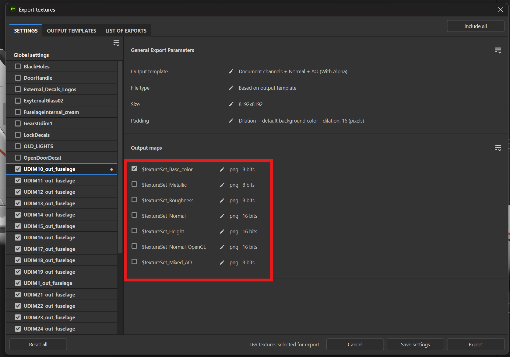
From there, I recommend clicking the Save Settings button, else you will have to redo this step if you close out the export window.
Once you are ready to export, you can go back to the Global Settings tab, verify that everything is as you want, and then click the Export button in the bottom right. Your textures will then compile and export as PNGs in your chosen directory.
And you are now done with Substance Painter! Everything else will be done via Photoshop/Paint.net/etc or even the package tool for converting from PNG to DDS, depending on your preference of program/workflow
Bonus | Black Masks and White Masks with Polygon Fill
These come in handy a ton, especially as your liveries get more complex and/or when you paint complex-shaped aircraft.
Let's take the COWS DA42 for example. You put stripes on the side, but you see that the fuselage and the engines are on the same material slot, meaning that your stripes show up both on the fuselage and the engine cowling since you are projecting from a left-side ortho view. That's a problem, right?
Black Mask time! Black masks when applied to a layer allow you to control where the paint is allowed to be, and where it isn't. Let's say we don't want the stripes on our M500 to go over the panel on the right side of the nose
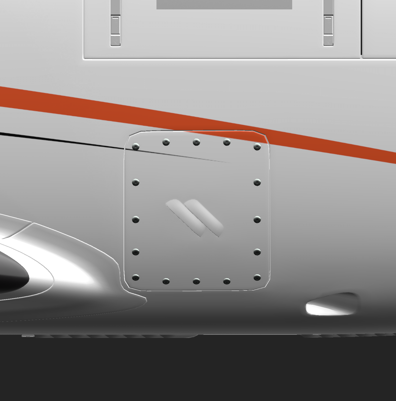
By default, the entire UV for this material is now "off limits" for the stripes layer. You can leave it as is, or you can customize the mask with a Polygon Fill. We'll try that.
On the left side toolbar, click the polygon fill tool
You'll see that the entire model now has a red wireframe around it. These are the 2D UVs now showing on the 3D model
We can use any of the 4 polygon selection tools to make our mask
Triangle. This allows you to select individual triangular facesSquare. This allows you to select individual quad facesCube. This allows you to select individual "parts", such as a pitot tube, a winglet, etcMesh Grid. This allows you to select UV islands
You will generally use a combination of 3-4 of these during painting, pretty much whatever works for your specific usecase at the time. Sometimes they work great, sometimes they are a little finnicky — it all depends on how the UVs are laid out for the model.
In this example, I'll use the square/quad selection. With this, wherever I click, it is added to the black mask, allowing the stripes to be visible in that area
On the contrary, we also have the option to use a White Mask.
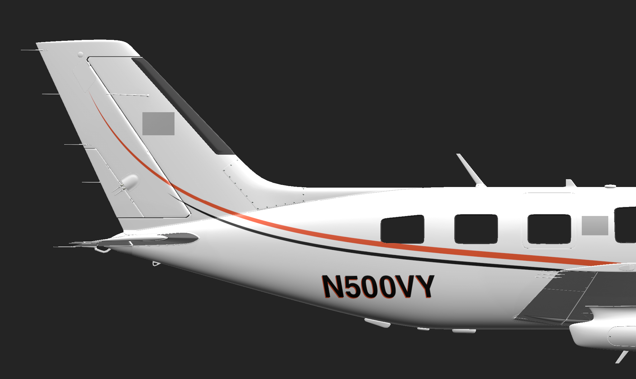
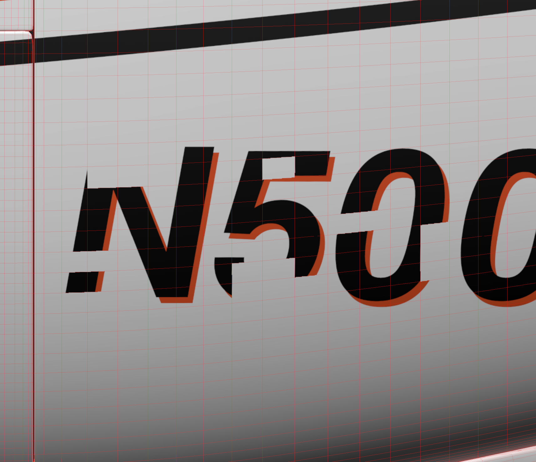
Similar to the Black Mask, but the inverse. When a White Mask is applied to a layer, by default, the entire layer is allowed to be visible. You can then use the polygon fill tool to select areas that you don't want to show up, essentially masking those out On the N-Number picture below, I've used a white mask + the polygon fill tool with the square/quad selection to remove some parts of the N-Number
And, a bit long winded, but I think that is roughly about all for now in terms of a basic tutorial.
Of course, with the M500, it is much more complex, but this should get you to the point of being able to make a nice livery. This whole thing will seem 10X easier on something like the Vision Jet, C172, DA62, etc, but you get the big picture here
Finishing
You need to convert png to DDS files you can use any image editor for that or the imagemagick convert tool.
The material names in Substance will be different than the DDS texture names, that's just an M500 thing.
For example, UDIM10_out_fuselage in Substance Painter translates to FSR_M500_OUT_FUSELAGE_BASECOLOR_OPACITY_1010.PNG.DDS
Instead of renaming them all, what I like to do is take all of the DDS files I need from the root FSR500 folder, open them all, and then just drag each of my PNGs on top of the materials and save as DDS. That way it just overwrites the DDS and I don't have to rename anything.
Then you put them in a livery diretory structure by using a template like this: FSR500 Livery Template.zip
Things you'll need to change/setup;
-
File name. This can be whatever you want. Right now it is named
livery-fsr500-xxx -
manifest.json. You'll want to change the title and creator to whatever you want
-
Third-level naming. Inside SimObjects>Airplanes, you'll see
z_fsreborn-fsr500-XXX. You can keep everything but the XXX, change that to whatever you want, such asz_fsreborn-fsr500-N123AB -
aircraft.cfg.
-
Title. Change the XXX in
"FSR500 XXX"to whatever you want -
Texture="". Change the"XXX"to whatever you name your texture.xxx folder to. For example, if it'stexture.N123AB, this line will beTexture="N123AB" -
ui_variation="". Change the XXX to whatever you want. This will be the name that shows up in the livery selection menu -
ui_createdby="". Change this to your name, nickname, whatever you want -
panel="". Change this to match your panel.xxx folder, similar to what you've done with the texture line and texture.xxx folder
-
-
texture.xxx. As described above, change the XXX to whatever you want, as long as it matched your aircraft.cfg. Inside of here is where your DDS files and corresponding .json files will go, you can copy them over from the FSR500 main folder. If you want 4096x4096 textures as a base, they are located at
...\fsreborn-aircraft-fsr500\SimObjects\Airplanes\fsreborn-fsr500\texture. If you want 2048x2048 textures as a base, they are located at...\fsreborn-aircraft-fsr500\SimObjects\Airplanes\fsreborn-fsr500\textures.lite. The texture.cfg you can leave alone since the fallbacks are already set -
panel.xxx. As described above, change the XXX to whatever you want, as long as it matches your aircraft.cfg. Inside of here is the panel.cfg, no need to touch that. Currently it is set up to have no dynamic registration, just hard painted registration. This only works in FS20 at the moment, as the FS24 registration is messed up and will show it anyways
No Comments